
")
Introduction:
The main objective of spinning is to produce yarn from fiber in textile industry, a bigger package of yarn is formed at the end with winding machine. It will ultimately lead to loss in production if efficiency or speed of cheese & cone forming process (i.e winding) is slower. Thus autoconer needs to run efficiently to fulfill all the requirements. There are some responsible causes that lower the efficiency of autoconer machine if we eliminate those causes no such problem will occur . Those problem cannot be recover by technical or non technical adjustments.During the internship I conducted study on Autoconer and found an effective way to improve the efficiency by using simple device with the lowest possible cost and effective working action. The efficiency of these device is calculated under the supervision of my guide at reputed textile mill in india and the study found to be successful.
PROBLEM IDENTIFICATION
Several companies are facing problem of stoppages on Ring frame machine due to lower production of Autoconer machine. The Ring frame can run effectively if autoconer works efficiently and give good production rate. So with a view to improve problem of efficiency I came up with project idea of “TO IMPROVE EFFICIENCY OF AUTO CONER MACHINE” which is linked with ring frame.
OBJECTS OF THE PROJECT
- Increase in efficiency of autoconer m/c so that production increases.
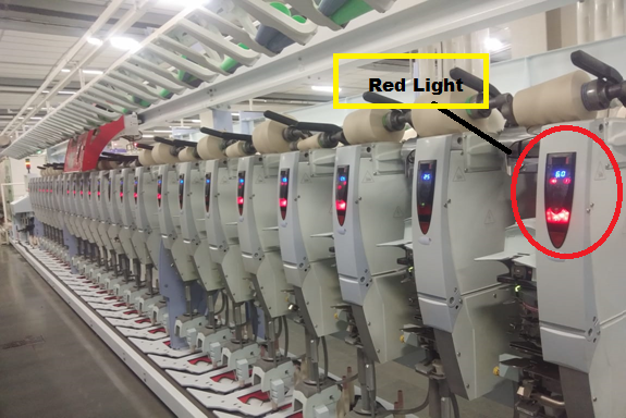
- Red light percentage is least in m/c so that there is no loss of efficiency.
- The worker should engage toward red light at the earliest and pay attention to the machine.
WORKING
OF AUTOCONER
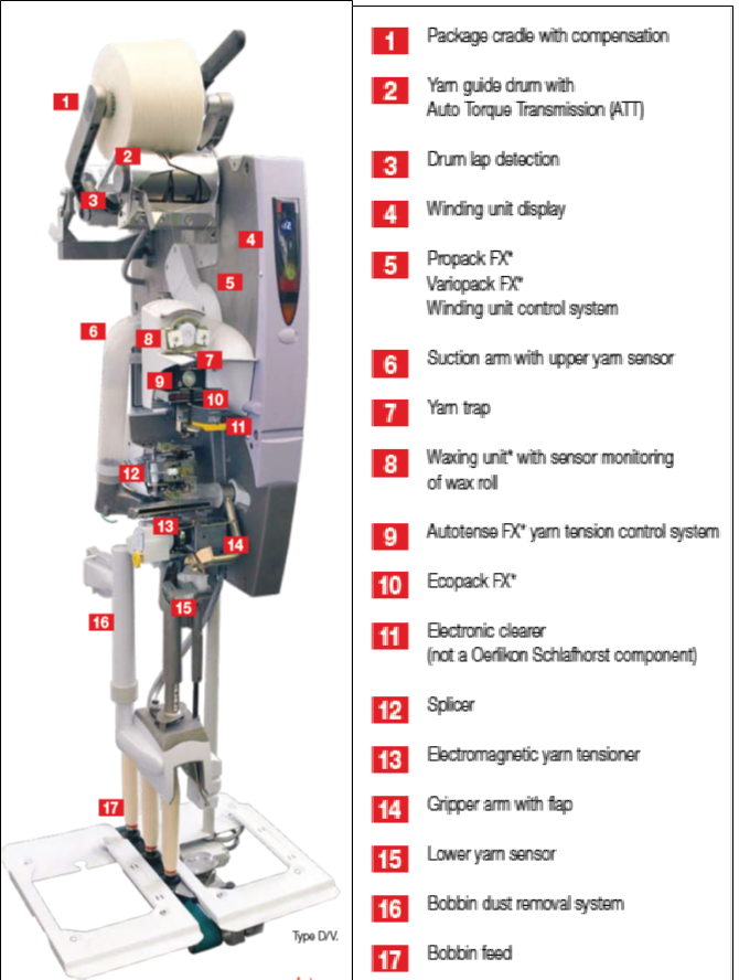
Schlafhorst Autoconer X5
is Linkconer attach with ring frame machine by an assembly where full bobbin is
transfer into the Autoconer machine and empty is revers into the ring frame
machine. The full bobbin is scan through a scanner where the amount of yarn
present is identified after that there is a suction plate which finds the end
of ring bobbin so that it is easier to find and get easy for passage of yarn.
The yarn passage is first start with a suction tube which feeds yarn bobbin end
to the bottom gripper through the tension plate the bottom suction holds the
bottom yarn. The upper arm suck the yarn from package and getting it in to
splicer where top and bottom yarn is gets spliced through the air splicer. The
splice yarn is now pass through the optical type of yarn clearing device
which identifies thick and thin places and remove it if any. Now with the help
of guide, yarn is wounds on package by the positively driven drum and wound on
the package in contact with the drum. The package is hold by the holder. There
is a provision of air break in handle, if yarn break, it is not allow the
package to rotate unnecessarily. The schematic diagram of a unit of Autoconer
machine is shown in figure 1.
 |
| Fig-1 |
REASONS FOR LOW EFFICIENCY OF LINKCONER MACHINE
As per the project, we have to found out the reason behind the low efficiency of machine. We did snap study of minimum 4 h per day for a week to find out the reasons. All the problems associated with stoppages of drum (Red Light) which ultimately lower the efficiency of machine efficiency were note down and identify the most occurring problems. Major technical reasons as well as some electrical and mechanical reasons for drum stop (Red Light) are mentioned and explained below.
- Upper end failure
- Bottom gripper
- Undersupply winding heads
- Worker negligence
- Electrical problems
Upper End Failure
This problem is occur when yarn clearer cut the yarn. The one end is goes into the suction at bottom and another one is goes into the package wound on drum. During splicing both upper and bottom yarn must be found out first and then they get assemble in the splicer assembly. But sometimes bottom ends found easily but the upper end stick to the package surface and upper suction arm did not able to found out this upper end and resulting in splicing failure. This is called upper suction arm failure. For the solution of this problem industry already installed SMART JET technology but not getting proper result.
Smart Jet
As per there is modern developments in the machine there is a new assembly called smart jet (this helps in finding out the missing upper end to the suction arm) is installed. In this technology, the jet of air flows blown on packet surface so that the broken upper end is easily detected and sucked by the upper suction arm. But the efficiency of this smart jet is not satisfactory. There is only slight improvement in production efficiency only. The efficiency of smart jet is about 48% to 50% only.
Bottom Gripper
Bottom gripper problem is happening when piecing of yarn in ring frame is not done properly or bobbin started by gaiting in the middle of doff of ring Bobbin. Due to this gripper did not found the yarn.
Worker Negligence
Some of lazy machine operator are busy with chatting with others and neglecting the problems associated on machine
Electrical Problems
The accidental breakdown of electrical parts like sensor or failure of batteries may results stoppage of whole machine.
CORRECTIVE ACTION
Corrective action taken to solve the upper end failure only which was the major technical problem. First trial was conducted by changing the RH of the winding section and further trial was conducted by implementing a newly device (Brush) in the mouth of upper suction arm. After successful implementation of brush further trail was taken after modification in the brush. These three trials are explain further section with their outputs.
Change in RH%
Due to the stickiness of package surface the broken end will not get found out by the upper suction arm that’s why we decided to change RH % of winding section. We changed the RH% from 60% to 58% in half of the machine . Results were compared before and after change in RH percentage from 1 to 52 and 53 to 104 . Trial was conducted for one day (24 h), one time only. Results showed reduction in upper end failure rate and reduction in red light percentage. From machine number 1 to 52 where Rh was not changed the value of suction failure is approximately same as earlier. But the value change from 244 to 160 in machine from 53 to 104 according to study of 104 machines for 20 minutes each. (Study was conducted between 11.00 to 2.00 pm)
Use of Brush
To reduce the problem of upper end failure, a new idea was implemented after taking approval from higher management that is USE OF BRUSH. Suction arm is not able to find broken yarn end from package surface to splice it with bottom yarn, resulting drum stop till operators attend that problem. So we made a brush for the reduction of upper end failure. We attached that brush on the suction arm plate as shown in figure 4. The Brush helps upper suction arm to find out that missing end on cone surface therefore drum does not stop further. The stoppages of machine reduced and machine efficiency ultimately increased.
Preparation of Brush
The brush is prepared by using paint brush having smooth bristles, thick paper, a stapler and a cello tape. At first, we take out the bristles of the brush (separate it from the brush head) and cut two strips of hard paper. Laying the brush bristles equally on the hard paper in such a way that the density of bristles should not be more and keeping some distance between them, staple all these bristles so that it is firmly fixed with the another strip of hard paper. Finally apply cello tape to ensure the firm fixing of bristles in the paper, the life of brush found more than 30 days doing successful operation.
 |
| Fig 3 |
 |
| Fig 4 |
Results before and after
brush trail
The trial is done on a machine at only on two drum i.e. drum no1 and 2 for 2 hours 47 minutes. Trial was found successful i.e. reduction in %SF i.e. upper end failure percentage. In drum one the % SF decreased from 3.1 to 1.1 and in drum 2 % SF decreased from 5.3 to 1.9. Below are the display of machine showing upper end failure percentage before using the brush on it and after the use of brush.
 |
| Fig 5 |
 |
| Fig 6 |
After that same trail was applied to machine number 33, 11 and 12 for all drums and found improved results as shown below.
Table- Results of brush trail
|
Machine No.-33 (Day 1) |
Before |
After 1h |
|
Count |
100S Supima |
100S Supima |
|
Production weight |
14.66kg |
21.45kg |
|
Red light% |
2.8 |
2.3 |
|
Efficiency |
46% |
57% |
|
Machine No.-11 (Day 2) |
Before |
After 1h |
|
Count |
100S Supima |
100S Supima |
|
Production weight |
34.5kg |
43.35kg |
|
Red light% |
3.4% |
2.6% |
|
Efficiency |
62% |
69% |
|
Machine No.-12 (Day 3) |
Before |
After 1h |
|
Count |
100S Supima |
100S Supima |
|
Production weight |
36.75 kg |
47.08kg |
|
Red light% |
4.9% |
4.0% |
|
Efficiency |
69.2% |
77.6% |
Modification of Brush
During use of brush, it was found that higher density of brush hairs disturbing the layer of yarn on cone surface that affects the quality of yarn as well as package. That’s why we have changed the density of brush (Figure 7) and thus increase the smoothness of brush which will not affect the quality of yarn as well as package.
 |
| Fig 7 |
Results before and after modified brush trail
Tables- Results of modified brush trail
|
Machine No.-11 (1 Day) |
Before |
After 1hrs |
|
Count |
100S Supima |
100S Supima |
|
Production weight |
39.07% |
47.08kg |
|
Red light% |
4.1% |
3.5% |
|
Efficiency |
65.5% |
77.6% |
|
Machine No.-12 (2 Day) |
Before |
After 1hrs |
|
Count |
100S Supima |
100S Supima |
|
Production weight |
47.07kg |
59.08kg |
|
Red light% |
4.9% |
3.7% |
|
Efficiency |
78.0% |
86.1% |
PROJECT CONCLUSION


)
4 Comments
Nice explanation of winding machine.
ReplyDeletewhat cause alarm ribbon breaker on spindles ? case autoconer x5
ReplyDeleteHOW WE CONTROL LOW EFF DRUMS
ReplyDeletePLS REPLY
ReplyDelete